Uart/jetson coms
This guide goes though adding UART communication between Jetson and type-c
Suppose you would like to send the x,y coordinates of armor panels your Jetson sees the type-c.
The simplest and and easiest way to do this it though UART.
Here is a basic video on how UART works at a low level if you have never heard of it before:
Materials
First lets wire up the hardware:
You will need 4 things
Jetson/any laptop with a USB port (laptop is recommended)
type-c
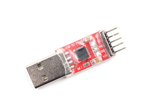
USB to UART converter (there are may USB to UART boards out there, I recommend this one)
type-c 4 pin UART cable
TODO: get pic
Wiring
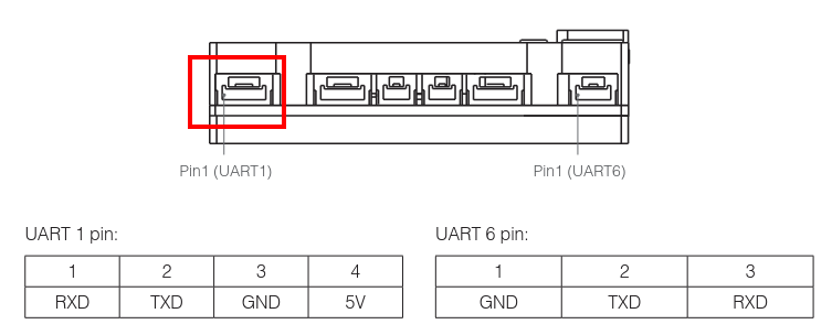
Plug in the 4 pin UART cable into the port shown below:
Connect RX of the type-c to the TX/TXD of USB to UART
and TX of the type-c to the RX/RXD of the USB to UART
Note: TX and TXD??
They mean the same thing in this context
TX == TXD
RX == RXD
UART1 but its UART2???
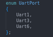
There are actual 3 different UART ports connected for the type-c
that is why in taproot there are these three in taproot/src/tap/communication/serial/uart.hpp
Here are the mappings of the board name with what is in taproot
| Board name (silk-screen) | Taproot / STM32 |
|---|---|
| UART2 | Uart1 |
| DBUS | Uart3 |
| UART1 | Uart6 |
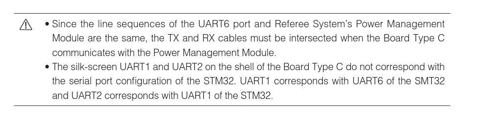
here is what the official DJI doc says:
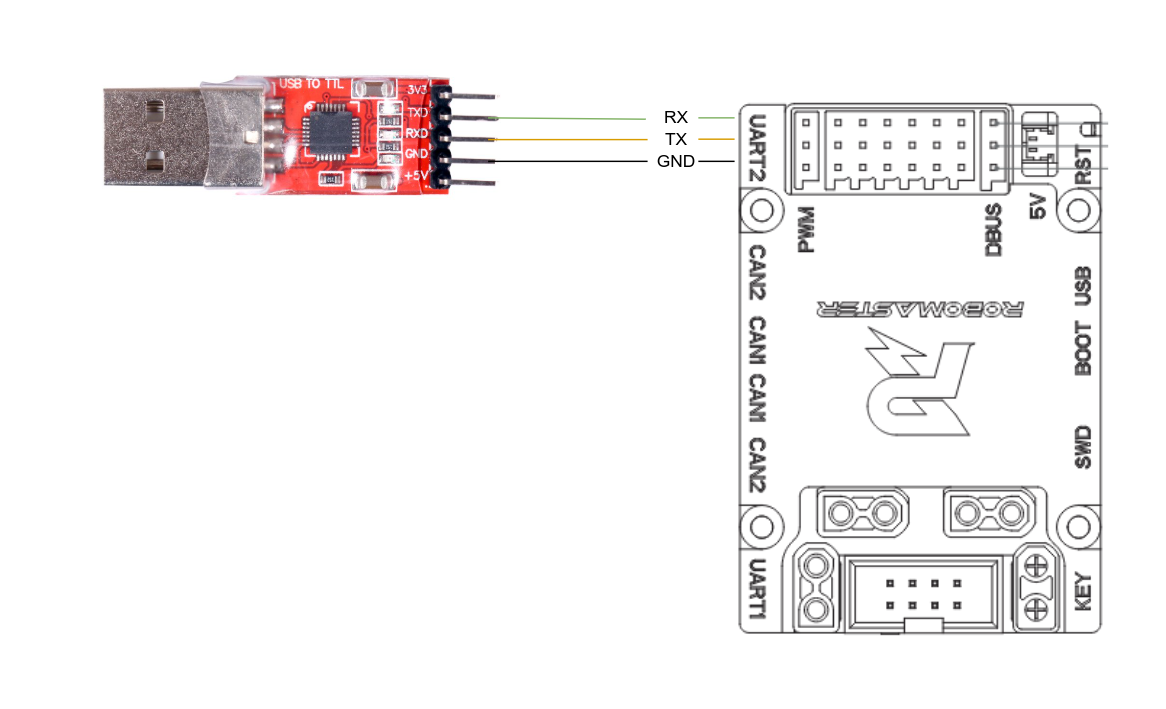
NOTE: MAKE SURE RX → TXD and TX → RXD (they must be “flipped”)
Why flipped?
TX stands for transfer and RX stands for receive.
you want the transfer pin off the USB to UART to go into the receive pin of the type-c and vice versa
Finally plug the USB to UART board into your laptop or Jetson
Software
We will first code the laptop/jetson side in python
UART settings
the settings the type-c in taproot uses are in this table below:
| Settings | Value |
|---|---|
| baud rate (bits/sec) | 115200 |
| byte size | 8 |
| parity | None |
| stop bits | one stop bit |
NOTE: the bytes are sent in little endian
Jetson code
install the pyserial library with pip to be able to send UART messages on your computer
pip install pyserial
If you have any questions below is the pyserial API
Official pyserial API: https://pyserial.readthedocs.io/en/latest/shortintro.html
Otherwise let us write a simple script to send a message over to the type-c
First find the port on linux the USB has been connected to by typing this command
ls /dev/tty*
you should get a list of files saying /dev/tty, /dev/tty0, /dev/tty1…
Looking for something close to /dev/ttyUSB0 or /dev/ttyUSB1. (In my case it was /dev/ttyUSB0)
To make sure that is the correct file/port unplug the USB to UART cable and run ls /dev/tty* again to check if it disappears and reconnect and run the command to see if it reapppears.
Next write this python script and for the argument for serial.Serial() put the port you USB to UART device appeared as
  import serial

ser = serial.Serial()                   # inits serial object
ser.port = '/dev/ttyUSB0'               # selects the port
ser.baudrate = 115200                   # set baudrate
ser.bytesize = serial.EIGHTBITS         # set byte size
ser.parity = serial.PARITY_NONE         # set parity bit
ser.stopbits = serial.STOPBITS_ONE      # set stop bit
ser.open()                              # opens the serial port
ser.write(b'hello')                     # write a string
ser.close()                             # close port
Note we applied the settings from here
Note: type-c max baud rate
according to ARUW the type-c can’t handle the max baud rate of the USB to UART chip (921,600) when using both RX and TX due to impedance.
this is why ARUW runs with separate UART ports each with one RX and one TX.
this script should just send the bytes hello on to the wire or exactly the bytes 0x68, 0x65, 0x6C, 0x6C, 0x6F.
| h | e | l | l | o |
|---|---|---|---|---|
| 0x68 | 0x65 | 0x6C | 0x6C | 0x6F |
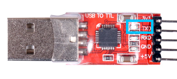
run the program and you should see the TXD led flash on the USB to UART board this just shows the actual 1s and 0s being sent on to the wire proving messages are being sent from the laptop/Jetson.
NOTE: this is a good debugging tool to check if stuff is being sent.
peeking into the wire?
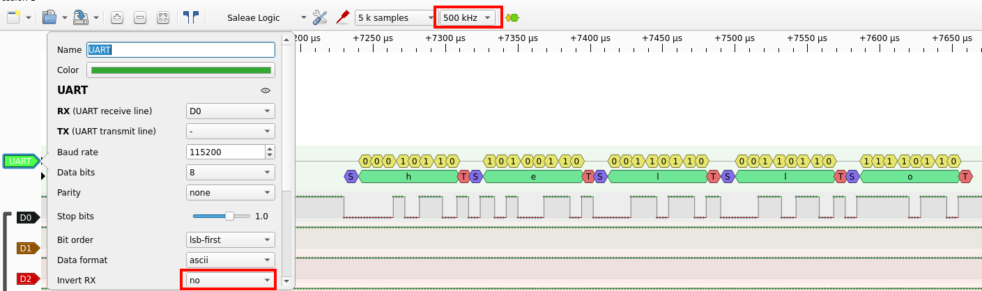
For those who are course or need to debug the connection you can buy a logic analyzer and connect it to the TX and GND of the USB to UART board to see the live bytes go out.
Make sure the settings are set correctly to correctly see the message
Type-c code
let us make every time we receive a message we flash the led
  #include "tap/board/board.hpp"  // import board specific settings

#include "drivers_singleton.hpp"  // import taproot

int main() {
    src::Drivers* drivers = src::DoNotUse_getDrivers();  // get the driver object
    Board::initialize();                                 // initialize the whole board

    const tap::communication::serial::Uart::UartPort port = tap::communication::serial::Uart::UartPort::Uart1;
    drivers->uart.init<port, 115200>();
    drivers->leds.init();  // initialize the led

    while (true) {

        uint8_t buff[5];                    // buffer to store the msg
        int read_len = drivers->uart.read(  // read the msg in from uart RX queue
            port,                           // port to read from
            buff,                           // where to store the msg
            5                               // read five bytes
        );

        char* msg = (char*)buff;  // cast the raw bytes(uint8_t) into a string

        // check if read in msg contains the string "hello"
        if (read_len != 0 && strncmp(msg, "hello", 5) == 0) {
            drivers->leds.set(tap::gpio::Leds::Red, true);  // Turn On LED
            modm::delay_ms(500);                            // sleep
        }
        drivers->leds.set(tap::gpio::Leds::Red, false);  // Turn On LED
        modm::delay_ms(500);                             // sleep
    }
}
compile and flash the code to the type-c and every time you run the python program on your laptop/Jetson the type-c
If you would like to check you can check each byte of buff (buff[0] , buff[1] , …) matches with the hello table above.
sending 2 floats
Let us now modify our code to send two floats over
  import serial
import struct

ser = serial.Serial()                   # inits serial object
ser.port = '/dev/ttyUSB0'               # selects the port
ser.baudrate = 115200 # set baudrate
ser.bytesize = serial.EIGHTBITS # set byte size
ser.parity = serial.PARITY_NONE # set parity bit
ser.stopbits = serial.STOPBITS_ONE # set stop bit
ser.open()

msg = struct.pack('<ff', 69.0, 420.0) # turns the floats into bytes in litte-endian

ser.write(msg)          # write two floats
ser.close()             # close port
to turn floats into bytes we will use the struct library
struct API: https://docs.python.org/3/library/struct.html
Note: we use little endian because ARM and most communication protocols use little endian
  #include "tap/board/board.hpp"  // import board specific settings

#include "drivers_singleton.hpp"  // import taproot

struct msg_format {  // creating  struct to received data
    float x;
    float y;
};

int main() {
    src::Drivers* drivers = src::DoNotUse_getDrivers();  // get the driver object
    Board::initialize();                                 // initialize the whole board

    const tap::communication::serial::Uart::UartPort port = tap::communication::serial::Uart::UartPort::Uart1;
    drivers->uart.init<port, 115200>();
    drivers->leds.init();  // initialize the led

    while (true) {
        int msg_size = sizeof(msg_format);
        uint8_t buff[msg_size];             // buffer to store the msg
        int read_len = drivers->uart.read(  // read the msg in from uart RX queue
            port,                           // port to read from
            buff,                           // where to store the msg
            msg_size                        // read five bytes
        );

        msg_format msg;                // where to store the msg
        memcpy(&msg, buff, msg_size);  // copy raw bytes into msg_format struct

        // check if read in msg contains the string "hello"
        if (read_len != 0 && msg.x == 69.0 && msg.y == 420.0) {
            drivers->leds.set(tap::gpio::Leds::Red, true);  // Turn On LED
            modm::delay_ms(500);                            // sleep
        }
        drivers->leds.set(tap::gpio::Leds::Red, false);  // Turn On LED
        modm::delay_ms(500);                             // sleep
    }
}
🎉CONGRATS!! YOU HAVE WORKING UART 🎉
At this point you can stop reading the guide and just use this setup.
However, there is a much safer and elegant way taproot provides for UART communication this next section goes over.