DJI serial
This guide goes though adding UART within Taproot
Data format
Taproot provides a class call DJISerial in taproot/src/tap/communication/serial/dji_serial.hpp
to use it you just extend the class and implement messageReceiveCallback()
the class expects your data to follow this format:
| Byte Number | Description |
|---|---|
| 0 | Frame Head Byte (0xA5) |
| 1 | Frame Data Length (Least significant Byte) |
| 2 | Frame Data Length (Most significant Byte) |
| 3 | Frame Sequence Number |
| 4 | CRC8 of the frame, (bytes 0 - 3) |
| 5 | Message Type (Least significant Byte) |
| 6 | Message Type (Most significant Byte) |
| Data Length | Body |
| … | … |
| 7 + Data Length | CRC16 (Least significant Byte) (bytes 0 - 6 + Data Length) |
| 8 + Data Length | CRC16 (Most significant Byte) |
here is the struct implementation in taproot if it makes it more clear:
      struct FrameHeader {
        uint8_t headByte;
        uint16_t dataLength;
        uint8_t seq;
        uint8_t CRC8;
    };

    struct SerialMessage {
        FrameHeader header;
        uint16_t messageType;
        uint8_t data[DATA_SIZE];
        uint16_t CRC16;
    };
Lets go though each field and explain them one by one:
Frame Head (
headByte)- DJI serial messages always start with the
0xA5byte. This way we know where the start of a frame is.
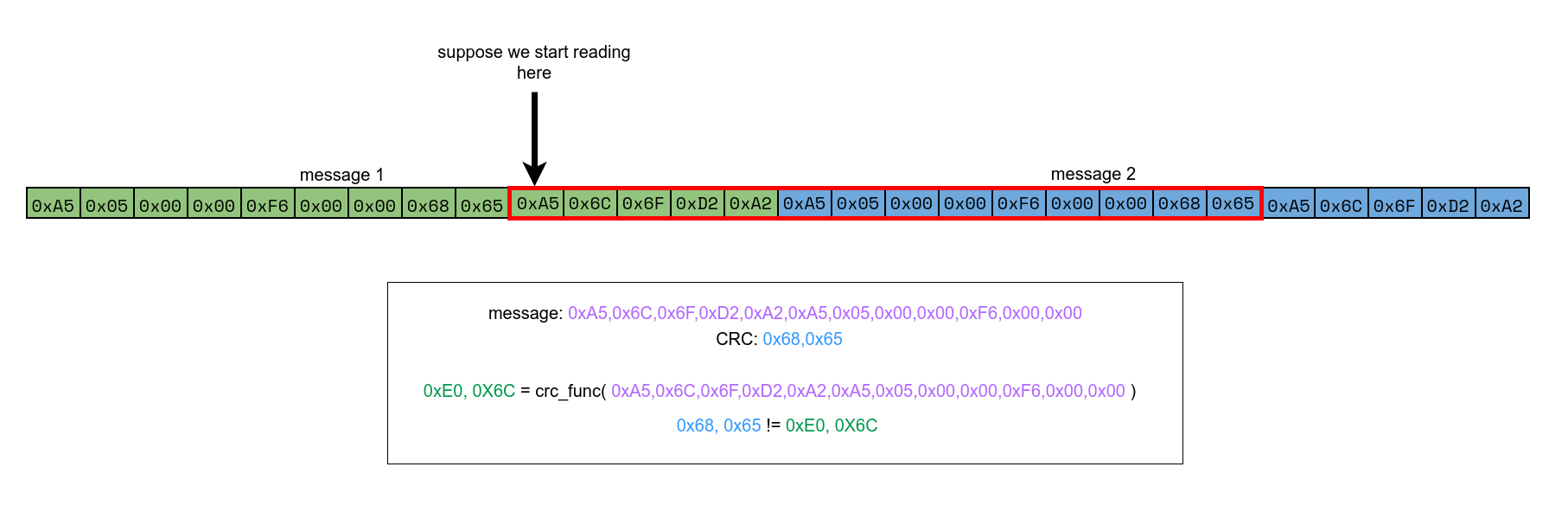
Why do we need a start byte?
Say the Jetson turns on first and the type-c second. Then the Jetson is already streaming stuff over. By the time the type-c turns on we don’t know where the start of the message is. If we were to read a single byte from UART with
drivers->uart.read()who knows what part of the message we are at. This is why we need a byte to indicate the start of the message. We would “dump” all the bytes before the0xA5and then we can start interpreting the bytes after.- DJI serial messages always start with the
Frame Data Length (
dataLength)- stores how long the Body (
data) section of the message will be. - NOTE: since we are using little endian the Least significant Byte comes first
- stores how long the Body (
Frame Sequence Number (
seq)- enumerates the messages, can be set to
0if you don’t care about using the sequence number
What is the point of sequence numbers?
Say I send three messages. Then the message sequence would be 0, 1, 2 for each message respectively The message sequence is designed so that if you drop a message we can easily tell which message it is. (EX: if we receive message 0, 1, 2, 4 then we know we dropped message 3) For more information on using sequence number search up TCP.
- enumerates the messages, can be set to
CRC8
- Checks if the
Frame Headeris “valid” - NOTE: if
0xA5(the start byte) is within in the body of the message the CRC check will make sure it is a valid frame alignment.
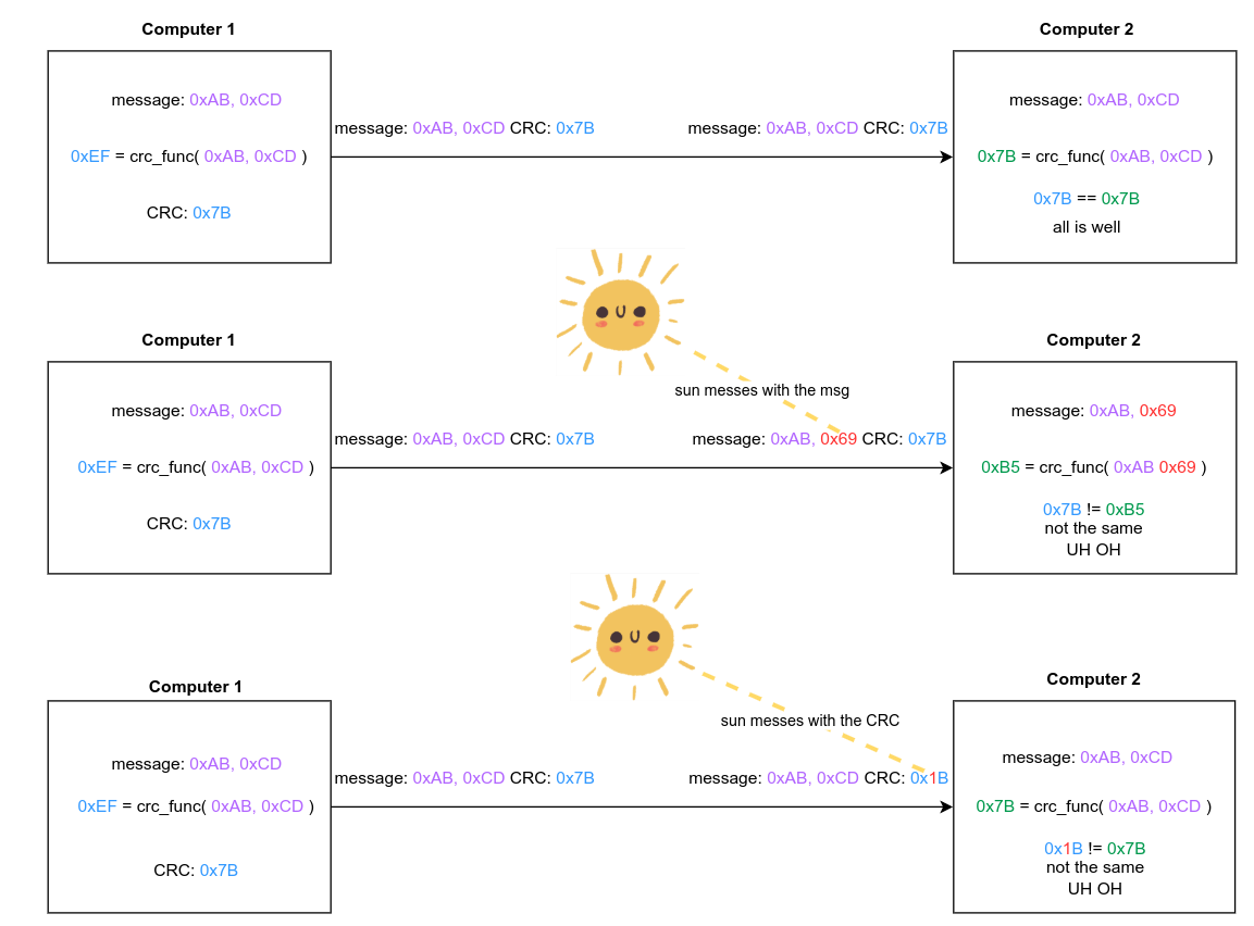
What is CRC?
CRC is a complicated error detection algorithm so I will give a simplified explanation here.
Think of CRC like a hashing algorithm.
Given a string a bytes I have this function, lets call it
crc_func(), that takes in the string of bytes and outputs a corresponding number.Then on a different computer when I go run the same
crc_func()on the same string of bytes I should revive the same exact number.This effectively given every message a unique CRC number.
If I send the string of bytes along with the corresponding CRC number then the other computer can check if the message if valid.
If for some reason a bit gets flipped while sending the message the CRC number would not line up showing that the message is not valid.
- Checks if the
Message Type (
messageType)- stores what kind of message is coming in, can be set to
0if you don’t care about message type
Example:
say you had a move chassis and a move gimbal message. Then you could have move chassis on Message Type 1 and move gimbal on Message Type 2. This can be done with Enums:
enum UartMessage : uint8_t{ MOVE_CHASSIS = 0, MOVE_GIMBAL = 1, ... };- stores what kind of message is coming in, can be set to
Body (
data)- Stores the literal bytes of the the message
- NOTE: it has a max of 1024 bytes specified in DJISerial
SERIAL_RX_BUFF_SIZEvariable
CRC16
- check if the whole message is “valid”
- what is CRC?
Example
lets take the “hello” message from earlier in the guide and put it in the DJI serial format
- “hello” takes 5 bytes so Frame Data Length = 5
- Sequence number will be set to 0
- CRC8:
0xF6 = crc8_func(0xA5, 0x05, 0x00, 0x00)Here is the full spec for the DJI CRC if you are curious: https://rm-static.djicdn.com/tem/17348/RoboMaster%20Referee%20System%20Serial%20Port%20Protocol%20Appendix%20V1.6%EF%BC%8820231124%EF%BC%89.pdf#%5B%7B%22num%22%3A127%2C%22gen%22%3A0%7D%2C%7B%22name%22%3A%22XYZ%22%7D%2C54%2C776%2C0%5D - Message Type will be set to 0
- body will equal = “hello”
- CRC16:
0x56, 0x34 = crc16_func(0xA5, 0x05, 0x00, 0x00, 0xF6, 0x00, 0x00, 0x68, 0x65, 0x6C, 0x6F)Here is the full spec for the DJI CRC if you are curious: https://rm-static.djicdn.com/tem/17348/RoboMaster%20Referee%20System%20Serial%20Port%20Protocol%20Appendix%20V1.6%EF%BC%8820231124%EF%BC%89.pdf#%5B%7B%22num%22%3A127%2C%22gen%22%3A0%7D%2C%7B%22name%22%3A%22XYZ%22%7D%2C54%2C776%2C0%5D
| Byte Number | Description | “hello” message value |
|---|---|---|
| 0 | Frame Head Byte (0xA5) | 0xA5 |
| 1 | Frame Data Length (Least significant Byte) | 0x05 |
| 2 | Frame Data Length (Most significant Byte) | 0x00 |
| 3 | Frame Sequence Number | 0x00 |
| 4 | CRC8 of the frame, (bytes 0 - 3) | 0xF6 |
| 5 | Message Type (Least significant Byte) | 0x00 |
| 6 | Message Type (Most significant Byte) | 0x00 |
| 7 | Body | 0x68 (h) |
| 8 | … | 0x65 (e) |
| 9 | … | 0x6C (l) |
| 10 | … | 0x6C (l) |
| 11 | … | 0x6F (o) |
| 12 = 7+5 | CRC16 (Least significant Byte) | 0x56 |
| 13 = 8+5 | CRC16 (Most significant Byte) | 0x34 |
The byte string to send this out comes out to being:
0xA5 0x05 0x00 0x00 0xF6 0x00 0x00 0x68 0x65 0x6C 0x6C 0x6F 0x56 0x34
Software implementation
Jetson software with DJI serial
install the crc library with pip to calculate CRC
pip install crc
python code:
  import serial
from crc import Calculator, Configuration

# Robomaster's MAXIM_DOW(the init value is different from Crc8.MAXIM_DOW)
RM_MAXIM_DOW = Configuration(
    width=8,
    polynomial=0x31,
    init_value=0XFF,
    final_xor_value=0,
    reverse_input=True,
    reverse_output=True,
)

# Robomaster's Kermit(the init value is different than Crc16.KERMIT)
RM_KERMIT = Configuration(
    width=16,
    polynomial=0x1021,
    init_value=0xFFFF,
    final_xor_value=0x0000,
    reverse_input=True,
    reverse_output=True,
)


crc8_calculator = Calculator(RM_MAXIM_DOW, optimized=True)  # Robomasters uses MAXIM_DOW for CRC8
crc16_calculator = Calculator(RM_KERMIT, optimized=True)  # Robomasters uses KERMIT for CRC16


def format_bytes(msg):
    return " ".join(f"0x{b:02x}" for b in list(msg))

def send(ser, data: bytes):
    start_of_frame = b'\xa5'
    data_len = len(data).to_bytes(2, byteorder='little') # converts data length into bytes and in little endian format
    frame_sequence_num = b'\x00'

    frame_header = start_of_frame + data_len + frame_sequence_num # creates frame header

    crc8 = crc8_calculator.checksum(frame_header).to_bytes(1, byteorder='little') # calculates crc8

    msg_type = bytes([0x00, 0x00]) # sets message type

    full_packet = frame_header + crc8 + msg_type + data # creates full packet
    crc16 = crc16_calculator.checksum(full_packet).to_bytes(2, byteorder='little') # calculates crc16

    msg = full_packet + crc16 # creates message to send

    print(format_bytes(msg)) # prints formated result

    ser.write(msg) # sends message to the type-c


ser = serial.Serial()
ser.port = '/dev/ttyUSB0'               # selects the port
ser.baudrate = 115200                   # set baud rate
ser.bytesize = serial.EIGHTBITS         # set byte size
ser.parity = serial.PARITY_NONE         # set parity bit
ser.stopbits = serial.STOPBITS_ONE      # set stop bit
ser.open()                              # opens the serial port
send(ser, b'hello')                     # sends the message
ser.close()                             # close port
running this code your printout should be:
![]()
Type-C code
  #include "tap/board/board.hpp"  // import board specific settings

#include "drivers_singleton.hpp"  // import taproot

using namespace tap::communication::serial;

class MyUart : public DJISerial {
public:
    MyUart(src::Drivers* drivers, Uart::UartPort port) : DJISerial(drivers, port) {};

    void messageReceiveCallback(const ReceivedSerialMessage& completeMessage) override {
        char buff[5];                           // where to store the msg
        memcpy(buff, completeMessage.data, 5);  // copy raw bytes into the buffer

				// checks if read in msg contains the string "hello"
        if (strncmp(buff, "hello", 5) == 0) {
            drivers->leds.set(tap::gpio::Leds::Red, true);  // Turn On LED
            modm::delay_ms(500);                            // sleep
        }
    }
};

int main() {
    src::Drivers* drivers = src::DoNotUse_getDrivers();  // get the driver object
    Board::initialize();                                 // initialize the whole board

    const Uart::UartPort port = Uart::UartPort::Uart1;
    MyUart myuart(drivers, port);

    myuart.initialize();
    drivers->leds.init();  // initialize the led

    while (true) {
        myuart.updateSerial();  // messageReceiveCallback gets called in here

        drivers->leds.set(tap::gpio::Leds::Red, false);  // Turn On LED
        modm::delay_ms(500);                             // sleep
    }
}
How does DJISerial work?
From a high level this is how it parses a message
In taproot/src/tap/communication/serial/dji_serial.cpp function updateSerial()
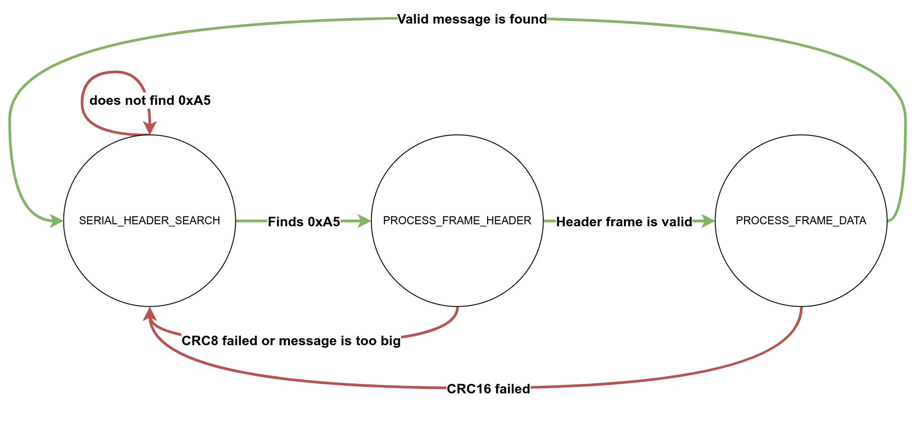
in each stage drivers->read() called with the READ() macro
in the PROCESS_FRAME_DATA messageReceiveCallback() gets called
Two floats example
NOTE: use
modm_packedit packs the struct as tightly as possible and removes padding
basically ensuring there are no extra bytes in between variables
Jetson code
  import serial
import struct
from crc import Calculator, Configuration

# Robomaster's MAXIM_DOW(the init value is different from Crc8.MAXIM_DOW)
RM_MAXIM_DOW = Configuration(
    width=8,
    polynomial=0x31,
    init_value=0XFF,
    final_xor_value=0,
    reverse_input=True,
    reverse_output=True,
)

# Robomaster's Kermit(the init value is different than Crc16.KERMIT)
RM_KERMIT = Configuration(
    width=16,
    polynomial=0x1021,
    init_value=0xFFFF,
    final_xor_value=0x0000,
    reverse_input=True,
    reverse_output=True,
)


crc8_calculator = Calculator(RM_MAXIM_DOW, optimized=True)  # Robomasters uses MAXIM_DOW for CRC8
crc16_calculator = Calculator(RM_KERMIT, optimized=True)  # Robomasters uses KERMIT for CRC16


def format_bytes(msg):
    return " ".join(f"0x{b:02x}" for b in list(msg))

def send(ser, data: bytes):
    start_of_frame = b'\xa5'
    data_len = len(data).to_bytes(2, byteorder='little') # converts data length into bytes and in little endian format
    frame_sequence_num = b'\x00'

    frame_header = start_of_frame + data_len + frame_sequence_num # creates frame header

    crc8 = crc8_calculator.checksum(frame_header).to_bytes(1, byteorder='little') # calculates crc8

    msg_type = bytes([0x00, 0x00]) # sets message type

    full_packet = frame_header + crc8 + msg_type + data # creates full packet
    crc16 = crc16_calculator.checksum(full_packet).to_bytes(2, byteorder='little') # calculates crc16

    msg = full_packet + crc16 # creates message to send

    print(format_bytes(msg)) # prints formated result

    ser.write(msg) # sends message to the type-c


ser = serial.Serial()
ser.port = '/dev/ttyUSB0'               # selects the port
ser.baudrate = 115200                   # set baud rate
ser.bytesize = serial.EIGHTBITS         # set byte size
ser.parity = serial.PARITY_NONE         # set parity bit
ser.stopbits = serial.STOPBITS_ONE      # set stop bit
ser.open()                              # opens the serial port
msg = struct.pack('<ff', 69.0, 420.0) # turns the floats into bytes in little-endian
send(ser, msg)                     # sends the message
ser.close()                             # close port
type-c
  #include "tap/board/board.hpp"  // import board specific settings

#include "drivers_singleton.hpp"  // import taproot

using namespace tap::communication::serial;

struct msg_formant {
    float x;
    float y;
} modm_packed;

class MyUart : public DJISerial {
public:
    MyUart(src::Drivers* drivers, Uart::UartPort port) : DJISerial(drivers, port) {};

    void messageReceiveCallback(const ReceivedSerialMessage& completeMessage) override {
        msg_formant msg;
        memcpy(&msg, completeMessage.data, sizeof(msg_formant));  // copy raw bytes into the buffer


        if (msg.x == 69.0 && msg.y == 420.0) {
            drivers->leds.set(tap::gpio::Leds::Red, true);  // Turn On LED
            modm::delay_ms(500);                            // sleep
        }
    }
};

int main() {
    src::Drivers* drivers = src::DoNotUse_getDrivers();  // get the driver object
    Board::initialize();                                 // initialize the whole board

    const Uart::UartPort port = Uart::UartPort::Uart1;
    MyUart myuart(drivers, port);

    myuart.initialize();
    drivers->leds.init();  // initialize the led

    while (true) {
        myuart.updateSerial();  // messageReceiveCallback gets called in here

        drivers->leds.set(tap::gpio::Leds::Red, false);  // Turn On LED
        modm::delay_ms(500);                             // sleep
    }
}
🎉If you have gotten to this part of the guide you have finished the taproot series 🎉
Here is one last resource you should read on implementing the communication protocols in C++: https://alex-robenko.gitbook.io/comms-protocols-cpp