Nav2 pt4 Lidar
What is Lidar?
Lidar (light detection and ranging) is using lases to determine how far objects are.
TODO
TODO:
link to add other sensors (realsense)
Often in robotics Odometry is updates very quickly but is prone to drift.
On the other hand Lidar is effectively “ground truth” because it can see the world around it however updates very slowly.
By using these two sensors together we can cover each others weaknesses.
In between the long update periods of Lidar we can use Odometry to get an accurate measurement of where we are. Then when the Lidar measurement eventually comes we correct the Odometry’s drift.
Just for this guide we will be sticking to a 2D Lidar but these instructions can be adapted to any kind of Lidar.
Nav2 expects Lidar data to be published on the /scan topic with type sensor_msgs/LaserScan
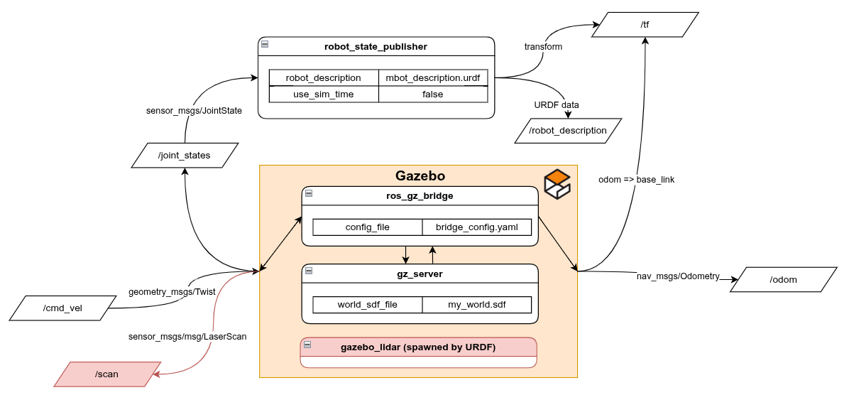
Simulating Lidar in Gazebo
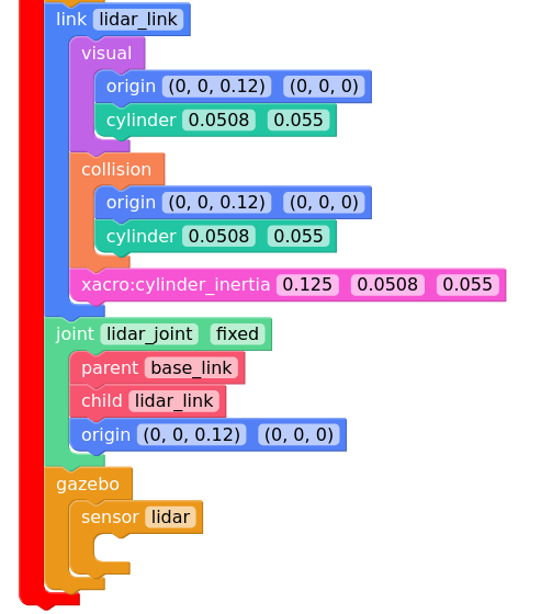
We must first add a Lidar link into our urdf to know where it is on the robot.
Also we have to add a Gazebo plugin to tell Gazebo simulate the Lidar
past this at the bottom of the file before the </robot> tag
  <link name="lidar_link">
    <visual>
      <origin xyz="0 0 0" rpy="0 0 0"/>
      <geometry>
        <cylinder radius="0.0508" length="0.055"/>
      </geometry>
    </visual>

    <collision>
      <origin xyz="0 0 0" rpy="0 0 0"/>
      <geometry>
        <cylinder radius="0.0508" length="0.055"/>
      </geometry>
    </collision>

    <xacro:cylinder_inertia m="0.125" r="0.0508" h="0.055"/>
  </link>

  <joint name="lidar_joint" type="fixed">
    <parent link="base_link"/>
    <child link="lidar_link"/>
    <origin xyz="0 0 0.12" rpy="0 0 0"/>
  </joint>


  <!-- 2D Lidar New Gazebo Sensor Plugin  -->
  <gazebo reference="lidar_link">
    <sensor name="lidar" type="gpu_lidar">
      <always_on>true</always_on>
      <visualize>true</visualize>
      <update_rate>5</update_rate>
      <topic>scan</topic>
      <gz_frame_id>lidar_link</gz_frame_id>
      <lidar>
        <scan>
          <horizontal>
            <samples>360</samples>
            <resolution>1.000000</resolution>
            <min_angle>0.000000</min_angle>
            <max_angle>6.280000</max_angle>
          </horizontal>
        </scan>
        <range>
          <min>0.120000</min>
          <max>12.0</max>
          <resolution>0.015000</resolution>
        </range>
        <noise>
          <type>gaussian</type>
          <mean>0.0</mean>
          <stddev>0.02</stddev>
        </noise>
      </lidar>
    </sensor>
  </gazebo>
Adding /scan topic in bridge_config.yaml
We have to bridge over the /scan topic from Gazebo
  - ros_topic_name: "/scan"
	gz_topic_name: "/scan"
	ros_type_name: "sensor_msgs/msg/LaserScan"
	gz_type_name: "gz.msgs.LaserScan"
	direction: GZ_TO_ROS
Run:
ros2 launch mbot_pkg display.launch.py use_sim_time:=True
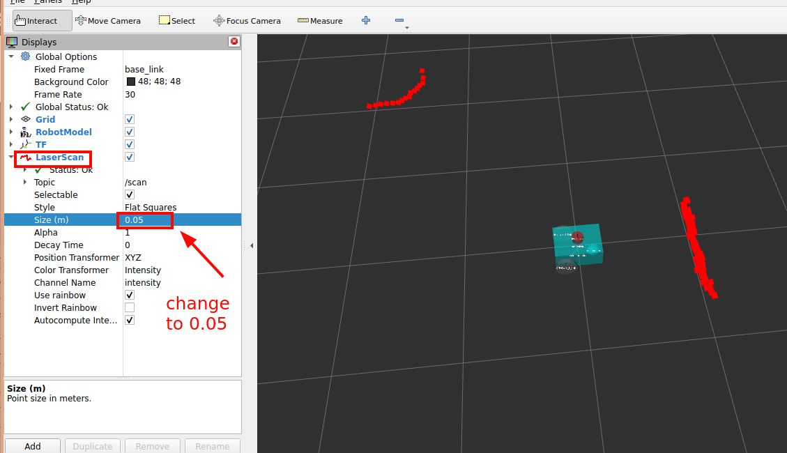
Lidar Rviz display
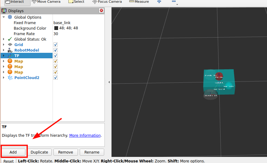
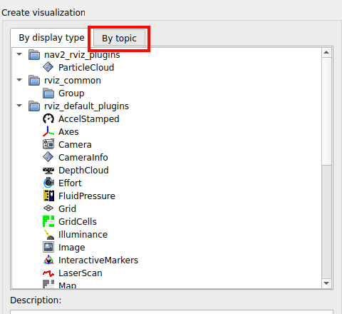
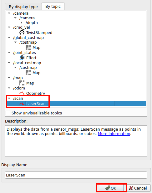
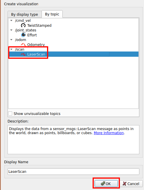
ctrl+s to save the config
Result:
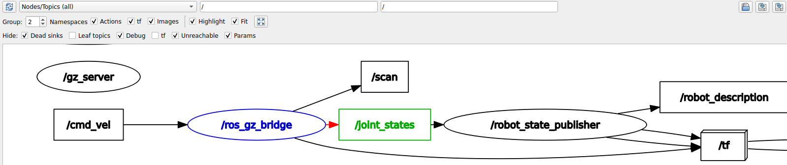
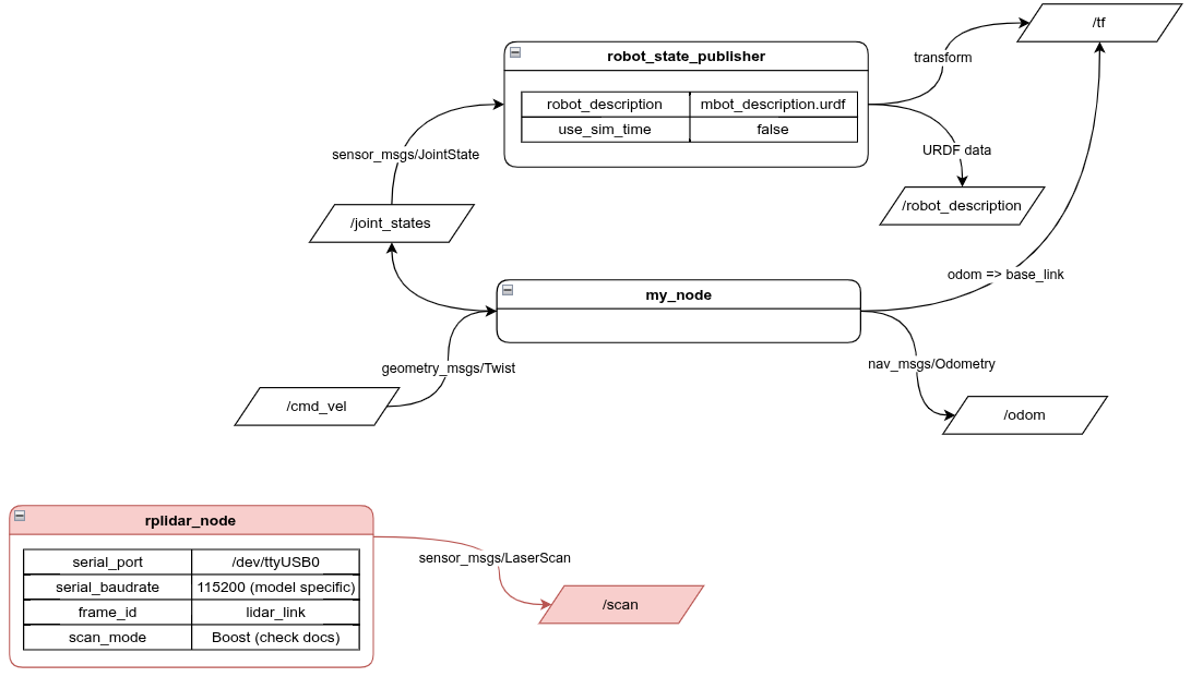
New node diagram
rqt_graph output:
Physical Lidar setup
For the physical Lidar this guide will use the RPLIDAR
If you have a different Lidar model refer to its documentation to set it up in ROS
Install
https://github.com/Slamtec/rplidar_ros/tree/ros2#compile–install-rplidar_ros-package
New Node
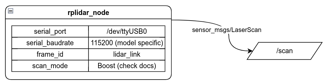
Outputs:
| Name | Type |
|---|---|
/scan | sensor_msg/LaserScan |
Params:
| Name | Type |
|---|---|
serial_port | string |
serial_baudrate | int (model specific) |
frame_id | string |
scan_mode | string |
description:
publishes the /scan topic for RPLIDAR products
Remember to disable gazebo nodes for physical setup
    return LaunchDescription([
        DeclareLaunchArgument(name='use_sim_time', default_value='False', description='Flag to enable use_sim_time'),
        # joint_state_publisher_gui_node, # debugs urdf joints
        my_node, # swaps joint_state_publisher_gui_node for physical robot
        robot_state_publisher_node, # publishes urdf to ROS
        rviz_node, # starts rviz

        # stuff to start gazebo
        # ExecuteProcess(cmd=['gz', 'sim', '-g'], output='screen'),
        # gz_server,
        # ros_gz_bridge,
        # spawn_entity,
    ])
Finding Lidar USB port:
ls /dev/ttyUSB*
If you are developing in a dev container you have to forward the USB port into the dev container.
in the file .devcontainer/devcontainer.json add this line into the runArgs: array
"--device=/dev/tty<your device>", to find what your device is outside of your devcontainer, probably in your WSL shell, run ls /dev/tty* to find which tty device to use. If you are not sure unplug and re run the command to see the difference.
you may also need to run sudo chmod 777 /dev/tty<your device> to use the device depending on how your hardware is setup
To launch the Lidar node use this command below.
NOTE: YOUR RPLIDAR MODEL MIGHT BE DIFFERENT
I am using the a2m8 model so I run the launch file below.
However, your model may be different so please look at this guide to find which launch file to run.
https://github.com/Slamtec/rplidar_ros/tree/ros2#run-rplidar-node-and-view-in-the-rviz
ros2 launch rplidar_ros view_rplidar_a2m8_launch.py scan_mode:=Boost serial_port:=/dev/ttyUSB0
ros2 launch mbot_pkg display.launch.py
New node diagram
Remember to add the /scan topic to rviz if you did save from above
Adding RPLidar to launch
idk tell them to look at the launch file to see which exact prams to put in
 def generate_launch_description():
		 ...

     lidar_node = Node(
        package='rplidar_ros',
        executable='rplidar_node',
        name='rplidar_node',
        parameters=[{'channel_type': 'serial',
                     'serial_port': '/dev/ttyUSB0', #recomended to do /dev/serial/by-path/...
                     'serial_baudrate': 115200,
                     'frame_id': 'lidar_link',
                     'scan_mode': 'Boost'}],
        output='screen')


    return LaunchDescription([
        DeclareLaunchArgument(name='use_sim_time', default_value='False', description='Flag to enable use_sim_time'),
        # joint_state_publisher_gui_node, # debugs urdf joints
        my_node, # swaps joint_state_publisher_gui_node for physical robot
        robot_state_publisher_node, # publishes urdf to ROS
        rviz_node, # starts rviz

        # stuff to start gazebo
        # ExecuteProcess(cmd=['gz', 'sim', '-g'], output='screen'),
        # gz_server,
        # ros_gz_bridge,
        # spawn_entity,

        lidar_node # lidar for physical setup
    ])
Result:
ros2 launch mbot_pkg display.launch.py use_sim_time:=True