Nav2 pt1 URDF
Original guide: https://docs.nav2.org/setup_guides/urdf/setup_urdf.html
This part of the guide goes over Nav2 which is a package in ROS that provides autonomous navigation.
In this guide we will build a simple differential drive (tank drive) robot
We will make both a simulated and physical robot
If you don’t have a physical differential drive robot you can build one following Articulated Robotics build guide to make:
Note: we wont use all the sensors in the this picture we mainly just need the Lidar and wheel encoders.
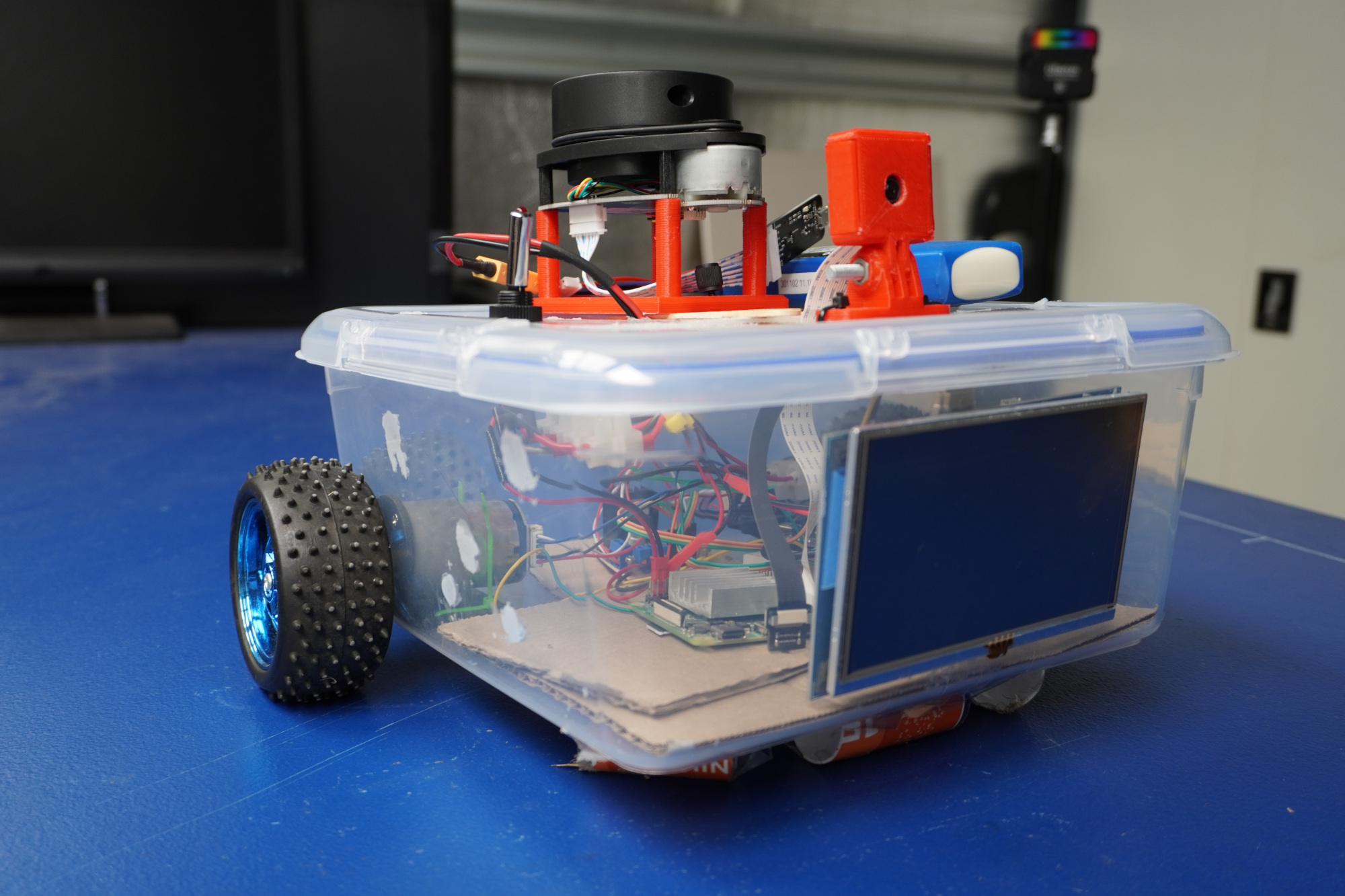
image courtesy of Articulated Robotics
Setup
I highly highly HIGHLY recommend first completing this guide on your laptop and just having a long cable connect to your robot’s sensors and motors
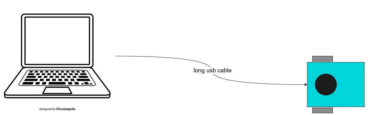
There are many reasons for this because
keeps all your code in one place
You don’t need a monitor, mouse, and keyboard to connect to your Raspberry Pi
Your laptop is much much faster than your Raspberry Pi so debugging is faster
Once you are done developing on your laptop all you have to do is copy all the files over to the Pi and Docker will automatically make it work
Creating workspace + package
What are ROS workspaces/packages?
  mkdir -p mbot_ws/src
cd mbot_ws/src
ros2 pkg create --build-type ament_python --license Apache-2.0 --node-name my_node mbot_pkg
Building
  cd ../ # you should be in the mbot_ws folder after running this
colcon build --symlink-install
source install/setup.bash
install pkg
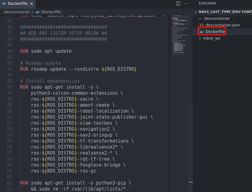
If you are doing the Dev container setup put these at the bottom of your Dockerfile in .devcontainer/Dockerfile
################################
## ADD ANY CUSTOM SETUP BELOW ##
################################
RUN sudo apt update
# Rosdep update
RUN rosdep update --rosdistro ${ROS_DISTRO}
# Install dependencies
RUN sudo apt-get install -y \
python3-colcon-common-extensions \
ros-${ROS_DISTRO}-xacro \
ros-${ROS_DISTRO}-ament-cmake \
ros-${ROS_DISTRO}-robot-localization \
ros-${ROS_DISTRO}-joint-state-publisher-gui \
ros-${ROS_DISTRO}-slam-toolbox \
ros-${ROS_DISTRO}-navigation2 \
ros-${ROS_DISTRO}-nav2-bringup \
ros-${ROS_DISTRO}-tf-transformations \
ros-${ROS_DISTRO}-librealsense2* \
ros-${ROS_DISTRO}-realsense2-* \
ros-${ROS_DISTRO}-rqt-tf-tree \
ros-${ROS_DISTRO}-foxglove-bridge \
ros-${ROS_DISTRO}-ros-gz
RUN sudo apt-get install -y python3-pip \
&& sudo rm -rf /var/lib/apt/lists/*
# enable extra quality of life plugins
RUN echo "source /usr/share/colcon_argcomplete/hook/colcon-argcomplete.bash" >> ~/.bashrc
RUN echo "source /usr/share/colcon_cd/function/colcon_cd.sh" >> ~/.bashrc
RUN echo "export _colcon_cd_root=/opt/ros/${ROS_DISTRO}/" >> ~/.bashrc
RUN echo "export RCUTILS_COLORIZED_OUTPUT=1" >> ~/.bashrc
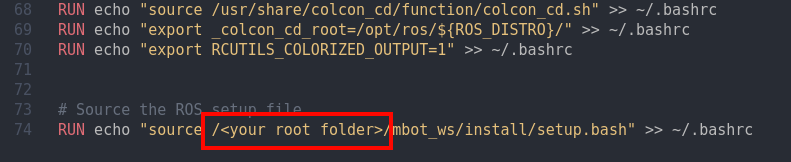
# Source the ROS setup file
RUN echo "source /<your root folder>/mbot_ws/install/setup.bash" >> ~/.bashrc
Example:
at the bottom of the Dockerfile file add this command with your path to the workspace
This makes it so you don’t have to source your environment every time
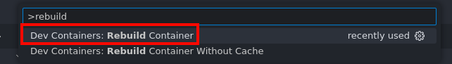
then rebuild the dev container by doing ctrl + shift + p type rebuild and select Rebuild Container
NOTE: every time you do an
apt install ...you need to add it to the dev container to make it stay permanently
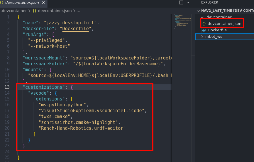
I also recommend you add these extensions to your dev container in devcontainer.json
    "customizations": {
    "vscode": {
      "extensions": [
        "ms-python.python",
        "VisualStudioExptTeam.vscodeintellicode",
        "twxs.cmake",
        "zchrissirhcz.cmake-highlight",
        "Ranch-Hand-Robotics.urdf-editor"
      ]
    }
  }
Install these packages (if you are not running the dev container setup)
  sudo apt install ros-$ROS2_DISTRO-joint-state-publisher-gui
sudo apt install ros-$ROS2_DISTRO-xacro
Building your robot in URDF
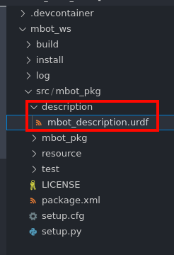
make a folder in mbot_pkg called description and a file called mbot_description.urdf
install this plugin if it is not already installed
Ctrl+Shift+P and select “Preview URDF”
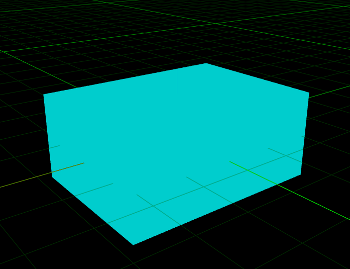
A new window should pop up
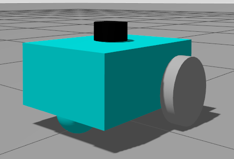
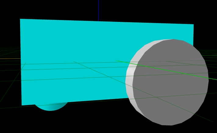
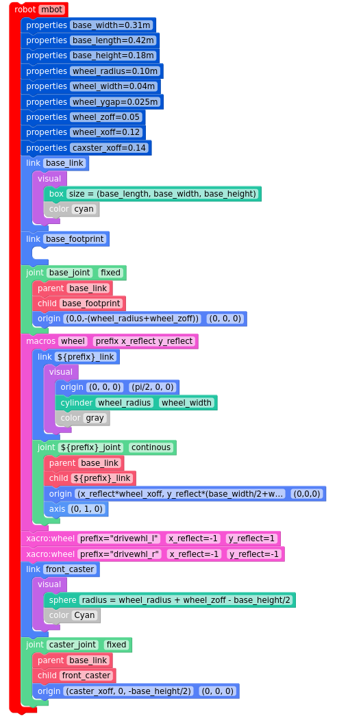
Here is a preview of robot we are going to make
urdf can get complex to look at so I will be putting a “scratch” like equivalent next to each example I put down.
To start add these tags:
  <?xml version="1.0"?>
<robot name="mbot" xmlns:xacro="http://ros.org/wiki/xacro">


</robot>
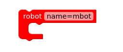
All urdf files must start with these tags to be valid urdf. All of our code will go in between the <robot> tags
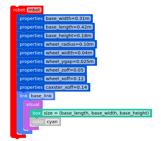
Next lets put down some constants we will use later
  <?xml version="1.0"?>
<robot name="mbot" xmlns:xacro="http://ros.org/wiki/xacro">
  <!-- Define robot constants -->
  <xacro:property name="base_width" value="0.31"/>
  <xacro:property name="base_length" value="0.42"/>
  <xacro:property name="base_height" value="0.18"/>

  <xacro:property name="wheel_radius" value="0.10"/>
  <xacro:property name="wheel_width" value="0.04"/>
  <xacro:property name="wheel_ygap" value="0.025"/>
  <xacro:property name="wheel_zoff" value="0.05"/>
  <xacro:property name="wheel_xoff" value="0.12"/>

  <xacro:property name="caster_xoff" value="0.14"/>


</robot>
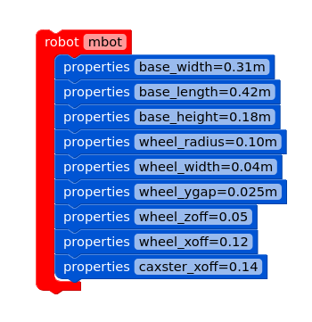
You can think of these as variables but in the xacro language
What do the variables represent?
base_width, base_length, base_height are the dimensions of the main body of the robot.
wheel_radius and wheel_width are the dimensions of the 2 back wheels.
wheel_ygap is the gap between the chassis and wheel.
wheel_zoff and wheel_xoff is the offset between the z-axis and x-axis.
caster_xoff is the offset of the caster wheel (the little ball) along the x-axis.
Lets now make a link for the body and call it base_link to be the “root” of our robot. This is common convention in ROS and is required to be called base_link for later parts in this guide
For now we are only going to add the visual part of the link to see if our design is correct. Later we will add collision and inertia.
    <!-- Robot Base -->
  <link name="base_link">
    <visual>
      <geometry>
        <box size="${base_length} ${base_width} ${base_height}"/>
      </geometry>
      <material name="Cyan">
        <color rgba="0 1.0 1.0 1.0"/>
      </material>
    </visual>

  </link>
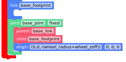
under </link> lets define a link called base_footprint. This link is just used for path finding to know where the robot is on a 2D map.
Later on in this guide we will see how it gets used.
    <!-- Robot Footprint -->
  <link name="base_footprint"/>

  <joint name="base_joint" type="fixed">
    <parent link="base_link"/>
    <child link="base_footprint"/>
    <origin xyz="0.0 0.0 ${-(wheel_radius+wheel_zoff)}" rpy="0 0 0"/>
  </joint>
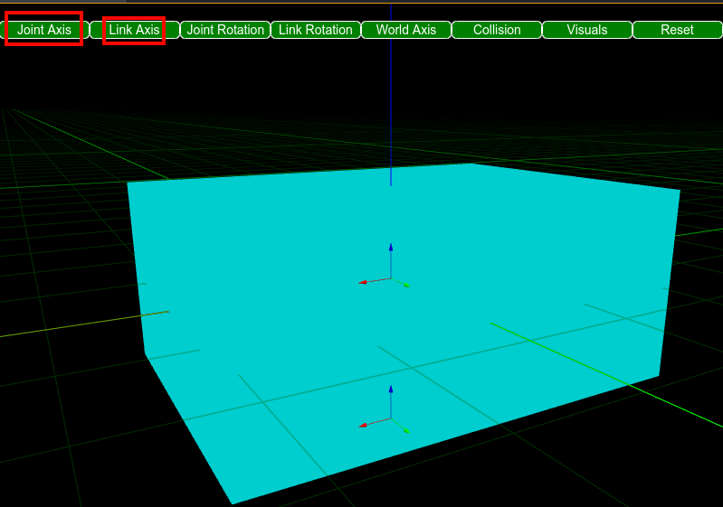
If you click on
Joint AxisandLink Axisyou can see thebase_linkandbase_joint
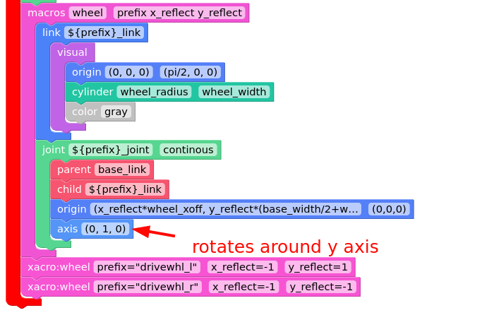
under </joint> to add wheels lets use a xacro:macro (basically a xacro function) to avoid duplicate code. The macro will take 3 functions prefix, x_reflect, and y_reflect so we can flip the wheel on the x or y axis. We also make the joint continuous so the wheel can rotate freely.
    <!-- Wheels -->
  <xacro:macro name="wheel" params="prefix x_reflect y_reflect">
    <link name="${prefix}_link">
      <visual>
        <origin xyz="0 0 0" rpy="${pi/2} 0 0"/>
        <geometry>
            <cylinder radius="${wheel_radius}" length="${wheel_width}"/>
        </geometry>
        <material name="Gray">
          <color rgba="0.5 0.5 0.5 1.0"/>
        </material>
      </visual>
    </link>

    <joint name="${prefix}_joint" type="continuous">
      <parent link="base_link"/>
      <child link="${prefix}_link"/>
      <origin xyz="${x_reflect*wheel_xoff} ${y_reflect*(base_width/2+wheel_ygap)} ${-wheel_zoff}" rpy="0 0 0"/>
      <axis xyz="0 1 0"/>
    </joint>
  </xacro:macro>

  <xacro:wheel prefix="drivewhl_l" x_reflect="-1" y_reflect="1" />
  <xacro:wheel prefix="drivewhl_r" x_reflect="-1" y_reflect="-1" />
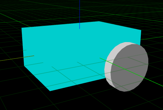
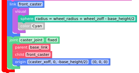
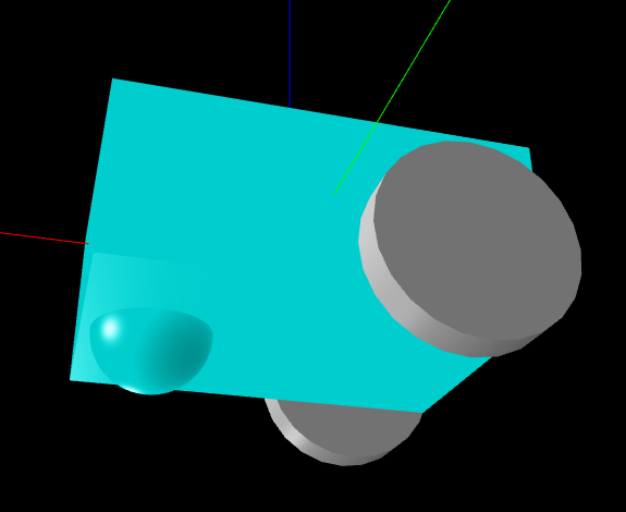
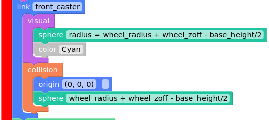
Under xacro:wheel lets add the caster wheel at the front of the robot. The robot up until now should look like the image below
    <!-- Caster Wheel -->
  <link name="front_caster">
    <visual>
      <geometry>
        <sphere radius="${(wheel_radius+wheel_zoff-(base_height/2))}"/>
      </geometry>
      <material name="Cyan">
        <color rgba="0 1.0 1.0 1.0"/>
      </material>
    </visual>
  </link>

  <joint name="caster_joint" type="fixed">
    <parent link="base_link"/>
    <child link="front_caster"/>
    <origin xyz="${caster_xoff} 0.0 ${-(base_height/2)}" rpy="0 0 0"/>
  </joint>
code up until this point
  <?xml version="1.0"?>
<robot name="mbot" xmlns:xacro="http://ros.org/wiki/xacro">

  <!-- Define robot constants -->
  <xacro:property name="base_width" value="0.31"/>
  <xacro:property name="base_length" value="0.42"/>
  <xacro:property name="base_height" value="0.18"/>

  <xacro:property name="wheel_radius" value="0.10"/>
  <xacro:property name="wheel_width" value="0.04"/>
  <xacro:property name="wheel_ygap" value="0.025"/>
  <xacro:property name="wheel_zoff" value="0.05"/>
  <xacro:property name="wheel_xoff" value="0.12"/>

  <xacro:property name="caster_xoff" value="0.14"/>

  <!-- Robot Base -->
  <link name="base_link">
    <visual>
      <geometry>
        <box size="${base_length} ${base_width} ${base_height}"/>
      </geometry>
      <material name="Cyan">
        <color rgba="0 1.0 1.0 1.0"/>
      </material>
    </visual>

  </link>

  <!-- Robot Footprint -->
  <link name="base_footprint"/>

  <joint name="base_joint" type="fixed">
    <parent link="base_link"/>
    <child link="base_footprint"/>
    <origin xyz="0.0 0.0 ${-(wheel_radius+wheel_zoff)}" rpy="0 0 0"/>
  </joint>

  <!-- Wheels -->
  <xacro:macro name="wheel" params="prefix x_reflect y_reflect">
    <link name="${prefix}_link">
      <visual>
        <origin xyz="0 0 0" rpy="${pi/2} 0 0"/>
        <geometry>
            <cylinder radius="${wheel_radius}" length="${wheel_width}"/>
        </geometry>
        <material name="Gray">
          <color rgba="0.5 0.5 0.5 1.0"/>
        </material>
      </visual>
    </link>

    <joint name="${prefix}_joint" type="continuous">
      <parent link="base_link"/>
      <child link="${prefix}_link"/>
      <origin xyz="${x_reflect*wheel_xoff} ${y_reflect*(base_width/2+wheel_ygap)} ${-wheel_zoff}" rpy="0 0 0"/>
      <axis xyz="0 1 0"/>
    </joint>
  </xacro:macro>

  <xacro:wheel prefix="drivewhl_l" x_reflect="-1" y_reflect="1" />
  <xacro:wheel prefix="drivewhl_r" x_reflect="-1" y_reflect="-1" />

    <!-- Caster Wheel -->
  <link name="front_caster">
    <visual>
      <geometry>
        <sphere radius="${(wheel_radius+wheel_zoff-(base_height/2))}"/>
      </geometry>
      <material name="Cyan">
        <color rgba="0 1.0 1.0 1.0"/>
      </material>
    </visual>
  </link>

  <joint name="caster_joint" type="fixed">
    <parent link="base_link"/>
    <child link="front_caster"/>
    <origin xyz="${caster_xoff} 0.0 ${-(base_height/2)}" rpy="0 0 0"/>
  </joint>

</robot>
Adding Collision and Inertia
Next lets add collision and inertia to our robot. These attributes will be used in the robot simulator later in this guide.
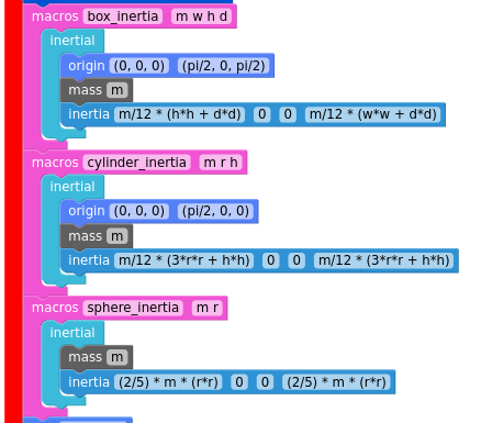
To start lets make some xacro:macro to avoid repetitive code to make box, cylinder, and sphere inertia.
Place this under the constants section.
    <!-- Define inertial property macros  -->
  <xacro:macro name="box_inertia" params="m w h d">
    <inertial>
      <origin xyz="0 0 0" rpy="${pi/2} 0 ${pi/2}"/>
      <mass value="${m}"/>
      <inertia ixx="${(m/12) * (h*h + d*d)}" ixy="0.0" ixz="0.0" iyy="${(m/12) * (w*w + d*d)}" iyz="0.0" izz="${(m/12) * (w*w + h*h)}"/>
    </inertial>
  </xacro:macro>

  <xacro:macro name="cylinder_inertia" params="m r h">
    <inertial>
      <origin xyz="0 0 0" rpy="${pi/2} 0 0" />
      <mass value="${m}"/>
      <inertia ixx="${(m/12) * (3*r*r + h*h)}" ixy = "0" ixz = "0" iyy="${(m/12) * (3*r*r + h*h)}" iyz = "0" izz="${(m/2) * (r*r)}"/>
    </inertial>
  </xacro:macro>

  <xacro:macro name="sphere_inertia" params="m r">
    <inertial>
      <mass value="${m}"/>
      <inertia ixx="${(2/5) * m * (r*r)}" ixy="0.0" ixz="0.0" iyy="${(2/5) * m * (r*r)}" iyz="0.0" izz="${(2/5) * m * (r*r)}"/>
    </inertial>
  </xacro:macro>
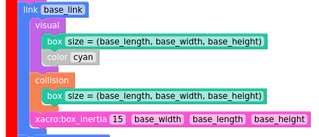
Next go into our base_link and add the collision and inertia tags.
    <!-- Robot Base -->
  <link name="base_link">
    <visual>
      <geometry>
        <box size="${base_length} ${base_width} ${base_height}"/>
      </geometry>
      <material name="Cyan">
        <color rgba="0 1.0 1.0 1.0"/>
      </material>
    </visual>

    <collision>
      <geometry>
        <box size="${base_length} ${base_width} ${base_height}"/>
      </geometry>
    </collision>

    <xacro:box_inertia m="15" w="${base_width}" d="${base_length}" h="${base_height}"/>
  </link>
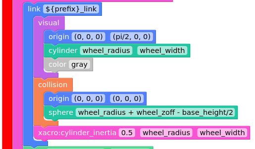
Same for our wheels:
      <link name="${prefix}_link">
      <visual>
        <origin xyz="0 0 0" rpy="${pi/2} 0 0"/>
        <geometry>
            <cylinder radius="${wheel_radius}" length="${wheel_width}"/>
        </geometry>
        <material name="Gray">
          <color rgba="0.5 0.5 0.5 1.0"/>
        </material>
      </visual>

      <collision>
        <origin xyz="0 0 0" rpy="${pi/2} 0 0"/>
        <geometry>
          <cylinder radius="${wheel_radius}" length="${wheel_width}"/>
        </geometry>
      </collision>

      <xacro:cylinder_inertia m="0.5" r="${wheel_radius}" h="${wheel_width}"/>
    </link>
and Same for the caster wheel:
    <!-- Caster Wheel -->
  <link name="front_caster">
    <visual>
      <geometry>
        <sphere radius="${(wheel_radius+wheel_zoff-(base_height/2))}"/>
      </geometry>
      <material name="Cyan">
        <color rgba="0 1.0 1.0 1.0"/>
      </material>
    </visual>

    <collision>
      <origin xyz="0 0 0" rpy="0 0 0"/>
      <geometry>
        <sphere radius="${(wheel_radius+wheel_zoff-(base_height/2))}"/>
      </geometry>
    </collision>

    <xacro:sphere_inertia m="0.5" r="${(wheel_radius+wheel_zoff-(base_height/2))}"/>
  </link>
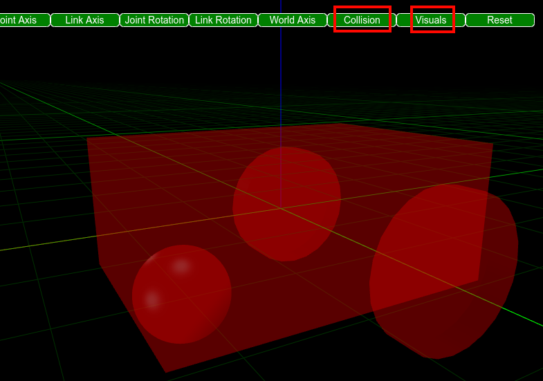
We can check our work if you click the Collision and Visuals buttons:
final code:
  <?xml version="1.0"?>
<robot name="mbot" xmlns:xacro="http://ros.org/wiki/xacro">

  <!-- Define robot constants -->
  <xacro:property name="base_width" value="0.31"/>
  <xacro:property name="base_length" value="0.42"/>
  <xacro:property name="base_height" value="0.18"/>

  <xacro:property name="wheel_radius" value="0.10"/>
  <xacro:property name="wheel_width" value="0.04"/>
  <xacro:property name="wheel_ygap" value="0.025"/>
  <xacro:property name="wheel_zoff" value="0.05"/>
  <xacro:property name="wheel_xoff" value="0.12"/>

  <xacro:property name="caster_xoff" value="0.14"/>

	<!-- Define inertial property macros  -->
  <xacro:macro name="box_inertia" params="m w h d">
    <inertial>
      <origin xyz="0 0 0" rpy="${pi/2} 0 ${pi/2}"/>
      <mass value="${m}"/>
      <inertia ixx="${(m/12) * (h*h + d*d)}" ixy="0.0" ixz="0.0" iyy="${(m/12) * (w*w + d*d)}" iyz="0.0" izz="${(m/12) * (w*w + h*h)}"/>
    </inertial>
  </xacro:macro>

  <xacro:macro name="cylinder_inertia" params="m r h">
    <inertial>
      <origin xyz="0 0 0" rpy="${pi/2} 0 0" />
      <mass value="${m}"/>
      <inertia ixx="${(m/12) * (3*r*r + h*h)}" ixy = "0" ixz = "0" iyy="${(m/12) * (3*r*r + h*h)}" iyz = "0" izz="${(m/2) * (r*r)}"/>
    </inertial>
  </xacro:macro>

  <xacro:macro name="sphere_inertia" params="m r">
    <inertial>
      <mass value="${m}"/>
      <inertia ixx="${(2/5) * m * (r*r)}" ixy="0.0" ixz="0.0" iyy="${(2/5) * m * (r*r)}" iyz="0.0" izz="${(2/5) * m * (r*r)}"/>
    </inertial>
  </xacro:macro>


  <!-- Robot Base -->
  <link name="base_link">
    <visual>
      <geometry>
        <box size="${base_length} ${base_width} ${base_height}"/>
      </geometry>
      <material name="Cyan">
        <color rgba="0 1.0 1.0 1.0"/>
      </material>
    </visual>

    <collision>
      <geometry>
        <box size="${base_length} ${base_width} ${base_height}"/>
      </geometry>
    </collision>

    <xacro:box_inertia m="15" w="${base_width}" d="${base_length}" h="${base_height}"/>
  </link>

  <!-- Robot Footprint -->
  <link name="base_footprint">
    <xacro:box_inertia m="15" w="${base_width}" d="${base_length}" h="${base_height}"/>
  </link>

  <joint name="base_joint" type="fixed">
    <parent link="base_link"/>
    <child link="base_footprint"/>
    <origin xyz="0.0 0.0 ${-(wheel_radius+wheel_zoff)}" rpy="0 0 0"/>
  </joint>


  <!-- Wheels -->
  <xacro:macro name="wheel" params="prefix x_reflect y_reflect">
    <link name="${prefix}_link">
      <visual>
        <origin xyz="0 0 0" rpy="${pi/2} 0 0"/>
        <geometry>
            <cylinder radius="${wheel_radius}" length="${wheel_width}"/>
        </geometry>
        <material name="Gray">
          <color rgba="0.5 0.5 0.5 1.0"/>
        </material>
      </visual>

      <collision>
        <origin xyz="0 0 0" rpy="${pi/2} 0 0"/>
        <geometry>
          <cylinder radius="${wheel_radius}" length="${wheel_width}"/>
        </geometry>
      </collision>

      <xacro:cylinder_inertia m="0.5" r="${wheel_radius}" h="${wheel_width}"/>
    </link>

    <joint name="${prefix}_joint" type="continuous">
      <parent link="base_link"/>
      <child link="${prefix}_link"/>
      <origin xyz="${x_reflect*wheel_xoff} ${y_reflect*(base_width/2+wheel_ygap)} ${-wheel_zoff}" rpy="0 0 0"/>
      <axis xyz="0 1 0"/>
    </joint>
  </xacro:macro>

  <xacro:wheel prefix="drivewhl_l" x_reflect="-1" y_reflect="1" />
  <xacro:wheel prefix="drivewhl_r" x_reflect="-1" y_reflect="-1" />

    <!-- Caster Wheel -->
  <link name="front_caster">
    <visual>
      <geometry>
        <sphere radius="${(wheel_radius+wheel_zoff-(base_height/2))}"/>
      </geometry>
      <material name="Cyan">
        <color rgba="0 1.0 1.0 1.0"/>
      </material>
    </visual>
    <collision>
      <origin xyz="0 0 0" rpy="0 0 0"/>
      <geometry>
        <sphere radius="${(wheel_radius+wheel_zoff-(base_height/2))}"/>
      </geometry>
    </collision>

  </link>

  <joint name="caster_joint" type="fixed">
    <parent link="base_link"/>
    <child link="front_caster"/>
    <origin xyz="${caster_xoff} 0.0 ${-(base_height/2)}" rpy="0 0 0"/>
  </joint>

</robot>
Nodes
Now that you have the urdf lets plug it in ROS
Here are some nodes to do so
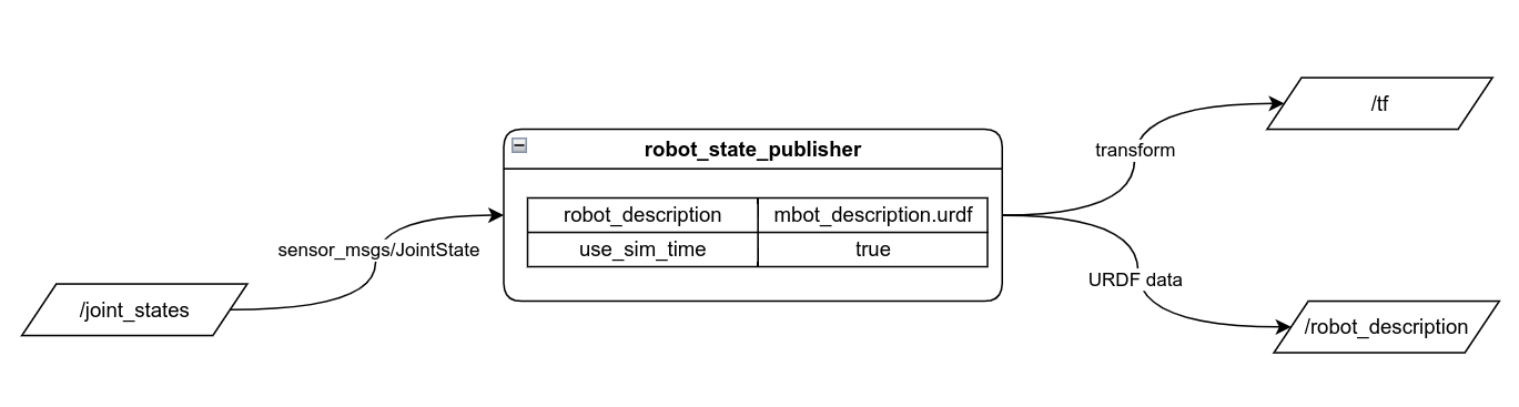
New Node robot_state_publisher
Inputs:
| Name | Type |
|---|---|
/joint_states | sensor_msg/JointState |
Outputs:
| Name | Type |
|---|---|
/tf | |
/robot_description |
Params:
| Name | Type |
|---|---|
robot_description | file |
use_sim_time | bool |
description:
Node that takes in the urdf and puts it into ROS
Takes 2 major inputs:
urdffile and publishes all transforms in the/tftopic/joint_statestopic that takes in all the states of joints in theurdf
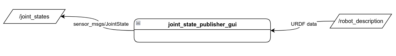
New Node joint_state_publisher_gui
Inputs:
| Name | Type |
|---|---|
/robot_description |
Outputs:
| Name | Type |
|---|---|
/joint_states | sensor_msg/JointState |
description:
lets you debug your urdf to see if all your joints work correctly.
Takes /robot_description from robot_state_publisher and outputs /joint_states with adjustable sliders
designed to be replaced by a physical robot or a simulated robot node
Current Node diagram
With the two nodes we are going to make this diagram:
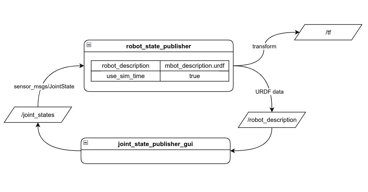
robot_state_publisher will publish the urdf. Any joints that are not static and need input will go into joint_state_publisher_gui and have a slider attached to it so we can debug it. Then it will be published back into robot_state_publisher. We can view what is happening with the /tf topic though rviz
Lets run these 2 nodes + rviz (to see our result) in 3 different terminals
ros2 run robot_state_publisher robot_state_publisher --ros-args -p robot_description:="$( xacro path/to/mbot_description.urdf )"
ros2 run joint_state_publisher_gui joint_state_publisher_gui
Download this config file and add it as argument for rviz2
rviz2 -d ./config.rviz
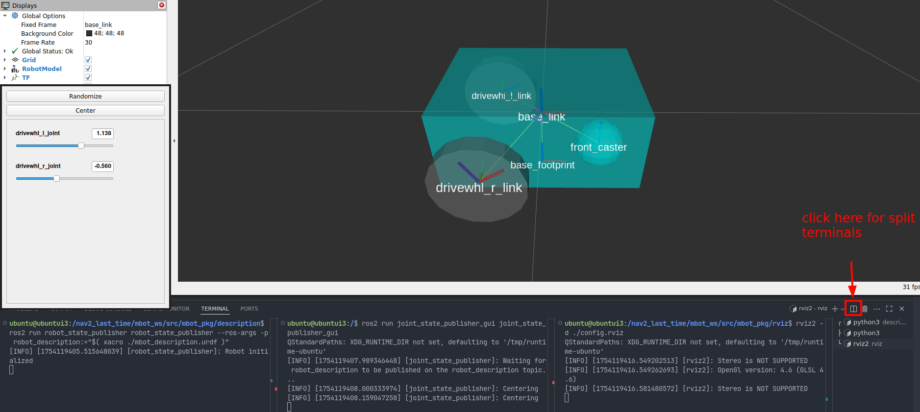
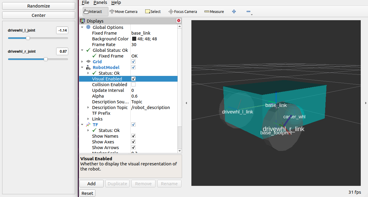
This should be the result:
You can move the sliders to move the wheels
No window appeared in Dev container?
If you are running Dev container and no windows pop up
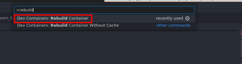
just rebuild the container:
to rebuild press ctrl+shift+P and type rebuild
Now lets create this node diagram by writing a launch file
Creating launch file
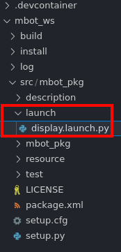
make a folder called launch and inside put display.launch.py
In the launch file we are going to spawn 3 nodes:
robot_state_publisherjoint_state_publisher_guirviz
Move config.rviz
What is rviz?
TODO: explain rviz better (say how it is like ros2 echo but visual)
create rviz folder in mbot_pkg and move the config.rviz:
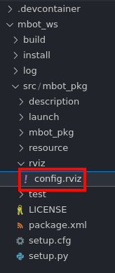
rviz file:
Launch file
What is in this launch file?
Launch files are just a scripted way of running multiple ROS nodes at the same time instead of opining multiple terminals.
This should do the same thing as running the three terminals from above
  import os
from launch import LaunchDescription
from launch.actions import DeclareLaunchArgument, ExecuteProcess, IncludeLaunchDescription
from launch.conditions import IfCondition, UnlessCondition
from launch.substitutions import Command, LaunchConfiguration
from launch_ros.actions import Node
from launch.launch_description_sources import PythonLaunchDescriptionSource
from ament_index_python.packages import get_package_share_directory
from ros_gz_bridge.actions import RosGzBridge
from ros_gz_sim.actions import GzServer
from launch_ros.substitutions import FindPackageShare


def generate_launch_description():
    pkg_share = get_package_share_directory('mbot_pkg') # gets the location of mbot_pkg
    default_model_path = os.path.join(pkg_share, 'description', 'mbot_description.urdf') # gets the location of the urdf
    default_rviz_config_path = os.path.join(pkg_share, 'rviz', 'config.rviz') # gets the location of the rviz config

    robot_state_publisher_node = Node(
        package='robot_state_publisher',
        executable='robot_state_publisher',
        parameters=[{'robot_description': Command(['xacro ', default_model_path])}]
    )
    joint_state_publisher_gui_node = Node(
        package='joint_state_publisher_gui',
        executable='joint_state_publisher_gui',
    )
    rviz_node = Node(
        package='rviz2',
        executable='rviz2',
        output='screen',
        arguments=['-d', default_rviz_config_path],
    )

    return LaunchDescription([
        joint_state_publisher_gui_node, # debugs urdf joints
        robot_state_publisher_node, # publishes urdf to ROS
        rviz_node # starts rviz
    ])
Add new files to setup.py
if we add new files types to the package we need to update the setup.py and rebuild
from setuptools import find_packages, setup
import os
from glob import glob

package_name = 'mbot_pkg'

files = []
for full_filepath in glob('**/*.*', recursive=True):
    filepath = os.path.split(full_filepath)
    if filepath[0] != '':
        result = (os.path.join('share', package_name, filepath[0]), [full_filepath])
        files.append(result)


setup(
    name=package_name,
    version='0.0.0',
    packages=find_packages(exclude=['test']),
    data_files=[
        ('share/ament_index/resource_index/packages',
            ['resource/' + package_name]),
        ('share/' + package_name, ['package.xml']),
    ] + files,


...
Build:
MAKE SURE YOUR RUN colcon build in mbot_ws folder!
colcon build --symlink-install
Running
To run the code we just need to do:
ros2 launch mbot_pkg display.launch.py
we can check which nodes are running with rqt_graph
In a new terminal tab, while rviz is still open, run rqt_graph
rqt_graph
Make sure you select Nodes/Topics (all) in the drop down (you also may need to press the refresh button to the left)
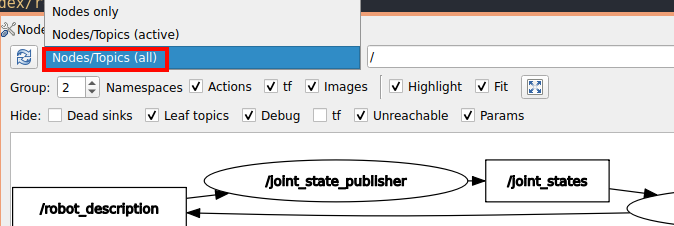
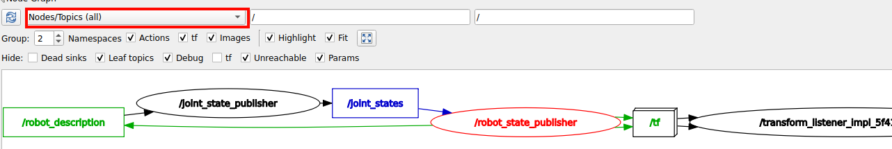
we will see it is matching our Node diagram from above
TODO: also add checkin points with file system idk
Final code
TODO: